
At the end of August I built the SparkPunk Sound Kit, and used an EHX 8-Step to trigger the kit via control voltage. Not long after this, Sparkfun released their own sequencer, which I promptly ordered, hoping it would arrive before the next electro-music festival.
The sequencer kit arrived well before the festival, but still required assembly. I spent the better part of an evening building this, for use in a gig three days later!
Sparkfun warns that this is not a kit for beginners, and I agree.

The first step for any kit like this is to check the parts list to make sure everything is there. I also use this time to organize like items, and pay close attention to anything tiny that I might lose. My kit was missing a resistor and – at first appearance – a small nut for the battery compartment. Fortunately, the resistor was easily replaced from my stock, and the nut turned up later, inside of a fader (apparently others have experienced this too).
The instructions Sparkfun provides on their web site are excellent. It pays to read through these once or twice before you build the unit, paying close attention to the images to gauge your progress. My one pet peeve is that they don’t call out the 5-pin connector early enough. If you get the two SparkPunk units together, then you can probably plan better. If you build them separately, you may run into a few issues if you do not plan ahead.

This kit involves a lot of repetition, placing the same sorts of parts. You can almost place all the resistors in one go, but I chose to break that into two steps.
The majority of the kit went together in under three hours. I’d recommend a break after hour two, as you may find that your concentration begins to wane from all of the close careful work.
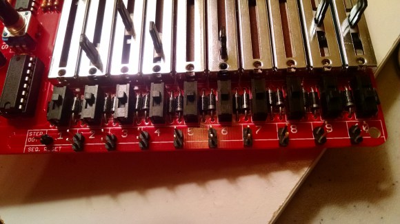
Some of my time was spent extracting the missing nut from a fader. I was pleased to get all of the faders lined up, only to get hung up on the last one a bit, so it is ever-so-slightly out of line. No big deal.

One of the things that made this kit go together so quickly was my new iron and pointed tip. This made quick work of the many diodes, resistors and transistors that normally would have tried my patience with my previous iron. There’s something to be said for quality tools.
On the flip side, until I got to one problem area at the end, I didn’t even use my vise or my third-hand. It wasn’t until I got to the 5-pin connector that I needed some extra help.


I’ve been trying to use sockets for ICs, and the kit didn’t come with any, but I had a couple 14 pin sockets around. The smaller ICs were set right into the board, another task easily accomplished with a variable temp iron.
The faders fit together nicely, provided you use painter’s tape. In fact, you might go through a good bit of painter’s tape on this kit, but it is totally worth it.

I ran into difficulty when I got to the 5-pin header on the left of the sequencer, which is made to marry up with the one on the SparkPunk Sound Kit. Since I built the sound kit much earlier, without an eye for using Sparkfun’s sequencer, I already had a layout for the header that wasn’t compatible (and even that ended up being my second try).
Now, with the sequencer, I had to decide if I wanted them to marry up as intended, or if I had enough headers/wires to make something else workable. The first attempt (shown above) involved headers coming straight up out of the sequencers, to be connected with some pre-fit wires.
This was enough to test the device, and confirm it was working (Yeah!) but I still didn’t like how it looked. I thought I’d try lining them up as intended, but this soon became mess because I had to first undo my previous soldering job. While this can be done in a pinch, you run the risk of blowing out the traces on the board.

By the time I landed on a solution, I had done just that… blew out the ground trace on the connector! For a moment the unit didn’t work at all, but luckily there was a ground nearby so I landed on the mangles solution below.

By this point my eyes were crossing and I was ready to stop. I’d have one day to mess around with this thing, then it was off to electro-music!
Here’s the first real test: